Introduction
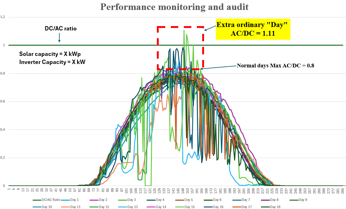
As solar photovoltaic (PV) systems continue to become a cornerstone of commercial and industrial energy infrastructure, maximizing system performance has become more important than simply installing more solar modules. While significant attention is often given to module efficiency and system capacity, one of the most critical—and frequently overlooked—factors influencing plant performance is inverter sizing and protection. A detailed performance audit of solar plants often reveals that inverter sizing decisions directly impact energy yield, system economics, and long-term reliability. The performance graph above demonstrates how daily generation patterns can vary significantly under different environmental conditions and why understanding the DC/AC relationship is essential for designing high-performance solar assets.
Understanding the DC/AC Ratio:
The DC/AC ratio represents the relationship between installed solar module capacity and inverter capacity.
DC/AC Ratio = Solar capacity (kWp)/Inverter capacity (kW)
Where:
- Solar capacity (DC): Total installed PV module capacity
- Inverter capacity (AC): Rated AC output capacity of the inverter
A DC/AC ratio greater than 1 indicates that the solar array is intentionally oversized relative to the inverter. This design approach is common in modern solar plants because modules rarely operate at their nameplate rating throughout the year. The challenge for designers is determining how much oversizing is economically and technically optimal.
What performance monitoring reveals
The graph shows normalized daily power output profiles over multiple operating days. Most days follow a smooth bell-shaped generation curve, reflecting the changing solar irradiance throughout the day.
Typical operating days
Under normal conditions:
- Peak AC output reaches approximately 80% of rated capacity.
- Inverters operate comfortably within their design limits.
- No significant clipping losses occur.
- System efficiency remains high throughout the day.
These operating conditions represent most of the annual solar production.
However, solar plants do not operate under "average" conditions every day.
The Extraordinary Day: Why Did the AC/DC Ratio reach 1.11?
One of the most interesting observations in the performance audit is the occurrence of an AC/DC ratio reaching approximately 1.11, significantly higher than the typical value of 0.8 observed on most days. At first glance, this may appear unusual or even indicate a measurement anomaly. It is a scientifically recognized phenomenon observed in solar plants worldwide.
1. Cloud Edge Enhancement Effect
The most significant contributor is the Cloud Edge Effect.
When broken clouds pass near the sun, cloud boundaries can act like large reflectors, concentrating additional sunlight onto the PV array. During these brief periods, irradiance levels can exceed standard test conditions (STC) and reach 1100–1300 W/m².
As PV output is nearly proportional to irradiance, a temporary 10–20% increase in sunlight can directly translate into higher power generation.
This phenomenon is commonly observed during partly cloudy days and is responsible for many short-duration power spikes recorded in utility-scale solar plants.
2. Lower Module Temperatures Increase Efficiency
Solar modules are rated under Standard Test Conditions:
- Irradiance: 1000 W/m²
- Cell Temperature: 25°C
In real operating conditions, especially during winter mornings or immediately after rainfall, module temperatures may be significantly lower. Silicon PV modules typically have a power temperature coefficient between -0.35% and -0.45% per °C. A module operating 20°C cooler than STC can produce approximately 8% more power than its rated output. This additional gain often coincides with cloud-edge events, creating ideal conditions for unusually high-power production.
3. Improved Atmospheric Conditions
Following rainfall or during cooler seasons:
- Airborne dust decreases.
- Atmospheric clarity improves.
- Solar radiation reaches the modules with less scattering loss.
These improved spectral conditions can provide an additional 1–3% increase in energy production.
4. Positive Module Manufacturing Tolerance
Most Tier-1 PV manufacturers deliver modules with positive power tolerance.
For example:
- Rated Power: 550 W
- Actual Delivered Power: 560–570 W
This means the installed array capacity may already be higher than the nominal design capacity, contributing additional generation during high-irradiance events.
5. Reflective Environmental Conditions
Temporary reflections from:
- White clouds
- Nearby buildings
- Water surfaces
- Light-colored roofs
can further increase incident solar radiation and produce short-duration power peaks.
Why This Matters for Inverter Sizing
The occurrence of an AC/DC ratio above 1.0 highlights a critical engineering reality:
Solar plants must be designed for extraordinary operating conditions, not just average ones.
If the inverter is undersized:
- Energy clipping increases.
- Valuable peak generation is lost.
- Annual energy yield decreases.
- Financial returns are reduced.
Conversely, selecting an excessively large inverter increases project cost without providing proportional benefits.
The goal is to identify the optimum balance between:
- Energy harvest
- Capital investment
- Equipment utilization
- Long-term reliability
A well-designed solar plant maximizes annual energy production while minimizing unnecessary capital expenditure.
The Often-Overlooked Role of Inverter Protection
Modern solar inverters do much more than convert DC power into AC power. They serve as intelligent protection systems that safeguard the entire solar asset.
Overcurrent Protection
Protects equipment against:
- String faults
- Internal inverter failures
- Excessive current conditions
Preventing damage to sensitive power electronic components.
Overvoltage Protection
Protects the plant from:
- Lightning-induced surges
- Grid disturbances
- Cold-weather voltage increases
Proper surge protection devices (SPDs) are essential for maintaining inverter reliability and reducing downtime.
Thermal Protection
Inverters continuously monitor internal temperatures and respond through:
- Dynamic derating
- Cooling system control
- Protective shutdown mechanisms
These functions significantly extend equipment life and prevent catastrophic failures.
Anti-Islanding Protection
When utility power is lost, the inverter must immediately disconnect from the grid to ensure:
- Personnel safety
- Utility compliance
- Equipment protection
This function is mandatory in grid-connected systems worldwide.
Advanced Grid Support Functions
Modern inverters continuously monitor:
- Voltage
- Frequency
- Harmonics
- Power factor
They automatically respond to abnormal grid conditions, improving both system stability and grid reliability.
Performance Monitoring: The Key to Continuous Optimization
A solar plant should never be considered a "set-and-forget" asset.
Continuous performance monitoring enables operators to:
Detect Inverter Clipping
Flat-topped power curves indicate potential clipping losses. Monitoring helps quantify:
- Lost energy
- Frequency of occurrence
- Financial impact
Validate Design Assumptions
Actual operating data confirms whether the selected DC/AC ratio is delivering the expected performance.
Identify Emerging Issues
Performance audits can reveal:
- Module degradation
- String mismatches
- Soiling losses
- Shading impacts
- Inverter faults
- Protection events
Early detection significantly reduces maintenance costs and minimizes revenue loss.
Best Practices for Commercial and Industrial Solar Projects, to maximize system performance and financial returns:
- Analyse site-specific irradiance data before design.
- Evaluate seasonal weather patterns and temperature variations.
- Account for cloud-edge enhancement effects.
- Optimize DC/AC ratio using detailed simulations.
- Quantify expected clipping losses.
- Select inverters with advanced protection and monitoring capabilities.
- Perform routine performance audits.
- Review annual operating data to identify optimization opportunities.
Register here (https://lnkd.in/g2r7qgKK) to those who are interested in participation to out training program. Training program details can be found here: https://lnkd.in/gCcuYyXj.
Let’s keep learning and growing together. If you're interested, you're welcome to join our WhatsApp group: (https://lnkd.in/gS-mrWEN)