
Modern hybrid energy systems cannot be designed using connected load assumptions alone especially when real operational data shows dynamic industrial behavior. Recently we analyzed load profiles of one of our client, the summary shared here clearly indicate that the facility behaves more like a microgrid with fluctuating industrial demand rather than a simple backup-load site. This blog breaks down the engineering insights derived directly from the load curves and translates them into practical design decisions for solar + BESS architecture. Microgrid with fluctuating industrial demand rather than a simple backup-load site.
Base load and operational pattern
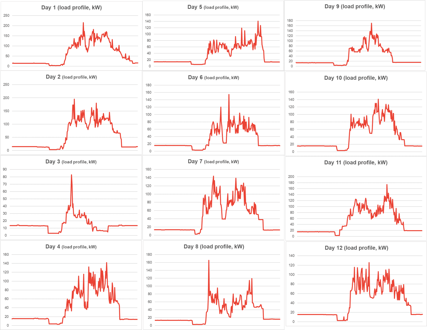
The facility shows a strong daytime operational signature:
Base load: ~10–20 kW during night/idle hours
Operating range: mostly between 60–140 kW
Peak demand: spikes reaching 180–220 kW
Operating window: roughly 6–8 hours of high activity daily
Load ramps are steep many days show sudden increases from base load to 60–100 kW within milli seconds, indicating motor-driven or compressor-based processes.
This behavior changes the entire design philosophy of the hybrid system.
Design around real operating load not connected load
Base load ≈ 10–20 kW
Normal operating band ≈ 60–120 kW
Peak transient load up to 200+ kW
Engineering strategy
Define three load layers:
Critical Load: 60–80 kW (continuous processes)
Operational Load: ~120 kW typical
Transient Peaks: up to 200 kW+
The battery PCS must be sized based on peak power, not average consumption. Designing only around energy capacity will result in instability during ramps.
Battery power rating vs energy rating
The load curves reveal a power-dynamic system, not an energy-heavy one.
Observations
Many spikes are short duration.
Long operating plateaus occur between 70–120 kW.
Design Implications
PCS overload capability ≥150% for motor starts.
Response time should be <20 ms to absorb sudden jumps (clear on Day 6 and Day 8).
Even if energy storage is ~700–800 kWh, inverter power should be at least 1.5× average operating load.
In simple terms: Power capability matters more than battery duration for stability.
Solar sizing strategy from daily load shape
The load is mostly daytime-driven with very low night consumption.
Solar Design Logic
Size PV to match the daytime plateau (80–120 kW).
Avoid oversizing PV beyond daytime consumption.
During outages:
Excess PV will be curtailed.
Battery may reach full SOC quickly, reducing efficiency.
Best strategy: Solar covers operational band, battery handles peaks.
Grid outage behavior & island mode stability
Sharp load transitions demand grid-forming capability.
Required features:
Grid-forming hybrid PCS
Droop control
Fast frequency stabilization
When load jumps from 20 kW to 80 kW suddenly, the battery must instantly regulate voltage and frequency otherwise the islanded system will trip.
Transient management
Vertical spikes visible in multiple days strongly suggest:
Motor starts
Compressor cycling
Heavy intermittent machinery
Engineering considerations
Short-term surge capability in PCS
Voltage sag tolerance
EMS-based staggered motor start
Possible VFD retrofit for largest loads
Without transient planning, island mode stability becomes unreliable.
EMS strategy tailored to the load pattern
The energy management system becomes the “brain” of this microgrid. Recommended EMS logic:
Maintain ~25% SOC reserve for outages
Use solar to maintain daytime SOC
Shed non-critical loads during islanding
Detect spike behaviour and temporarily increase discharge limits
This transforms BESS from a backup system into an active power stabilizer.
Transfer time & automation sensitivity
The industrial load profile suggests automation equipment.
Design Decisions
If PLC/SCADA is present → transfer time <20 ms
If not → 100 ms ATS may be acceptable
Fast transfer prevents process interruption during outages.
Protection philosophy for fluctuating loads
Dynamic industrial loads require adaptive protection settings:
Dynamic current limits
Adaptive protection curves
Reverse power blocking during PV surplus
Static protection schemes often fail in hybrid microgrids.
Battery duration strategy smarter backup planning
From the graphs:
High load lasts only 6–8 hours daily.
Base load remains low for long periods.
Cost optimization
Instead of designing for full-load backup all day:
Full power backup for 1–2 hours
Extended backup for reduced critical load
This significantly optimizes BESS cost without compromising resilience.
Practical engineering recommendations
Translating the load curves into real design numbers:
- Hybrid PCS rating: 150–200 kW class
- Battery energy: ~768 kWh suitable for multi-hour support
- Solar sizing: 80–120 kWp, aligned with operating plateau
- Mandatory grid-forming architecture
Why this is a microgrid, not just backup
Load profiles studies clearly demonstrate :
- Industrial ramp behavior
- High transient peaks
- Strong daytime energy demand
- Peak shaving
- Power smoothing
- Reduced DG runtime
- Improved operational resilience
For any requirements, technical discussions, or project support related to BESS, hybrid solar solutions, consulting, lender and owner engineering or microgrid applications, please feel free to reach out to our team at info@raygentenergy.com. We will be happy to understand your application needs and provide the right engineering support for your project.